In-Circuit Test (ICT) vs Functional Test: Which Does Your PCB Need?
ICT tells you the board was built right; functional testing tells you it works. How they differ, and how to combine them sensibly.
Inspection tells you a board looks right. Testing tells you it is right. There are two main kinds of electrical test, and they answer different questions. Choosing between them, or combining them, depends on your board, your volume and what a field failure would cost you.
In-circuit testing (ICT)
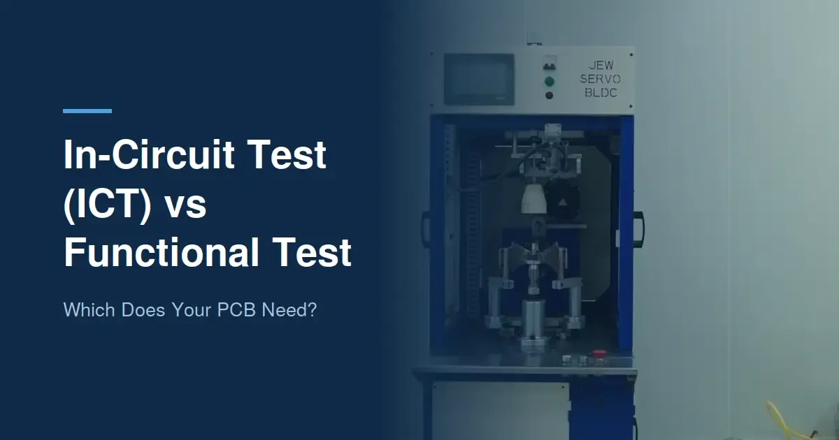
What it is: the board sits on a fixture, often called a bed of nails, with spring-loaded probes touching test points on every net. The tester then checks each component and connection individually: shorts and opens, resistor and capacitor values, diode orientation, and often basic IC presence.
What it is good at:
- pinpointing the exact faulty part or joint, so repair is quick;
- catching manufacturing faults that a functional test might miss, like a wrong-value resistor that still lets the board "work";
- speed on the line: once the fixture exists, each board takes seconds.
Its limits: fixtures cost money and take time to build, and every net needs an accessible test point, which has to be planned in layout. ICT also does not prove the board works as a system.
Flying probe: ICT without the fixture
A flying probe tester uses a few moving probes instead of a fixed bed of nails. It is slower per board but needs no fixture, which makes it a good fit for prototypes and low-volume builds where a fixture would never pay for itself.
Functional testing (FCT)
What it is: the board is powered up, usually in a test jig that simulates its real environment, and checked against what it is supposed to do. Inputs are applied, outputs measured, firmware loaded and run, and communication interfaces exercised.
What it is good at:
- proving the board does its job;
- catching problems ICT cannot see, such as firmware issues, timing faults, or a component that measures fine but fails under load;
- being designed around your product's real use.
Its limits: when a board fails, the test says what failed, not always why, so diagnosis takes longer. Each product needs its own test procedure and jig.
Side by side
ICT / flying probe | Functional test | |
|---|---|---|
Question it answers | Was it built correctly? | Does it work? |
Board state | Unpowered or partly powered | Fully powered, running |
Fault diagnosis | Points to the exact part or net | Points to a function |
Setup | Fixture (ICT) or program (flying probe) | Test procedure and jig |
Best for | Higher volumes, dense boards | Every product, all volumes |
Choosing a test strategy
A simple way to think about it:
- Prototypes: functional bench testing, with flying probe if the board is dense or expensive.
- Low volume: functional testing on a jig, plus flying probe where fault coverage matters.
- High volume: ICT on the line to catch build faults fast, then functional testing to prove the product.
Whatever you choose, plan test access during layout. Adding test points after the board is fabricated is not an option. Our DFM guide covers this.
Testing at Polyfit
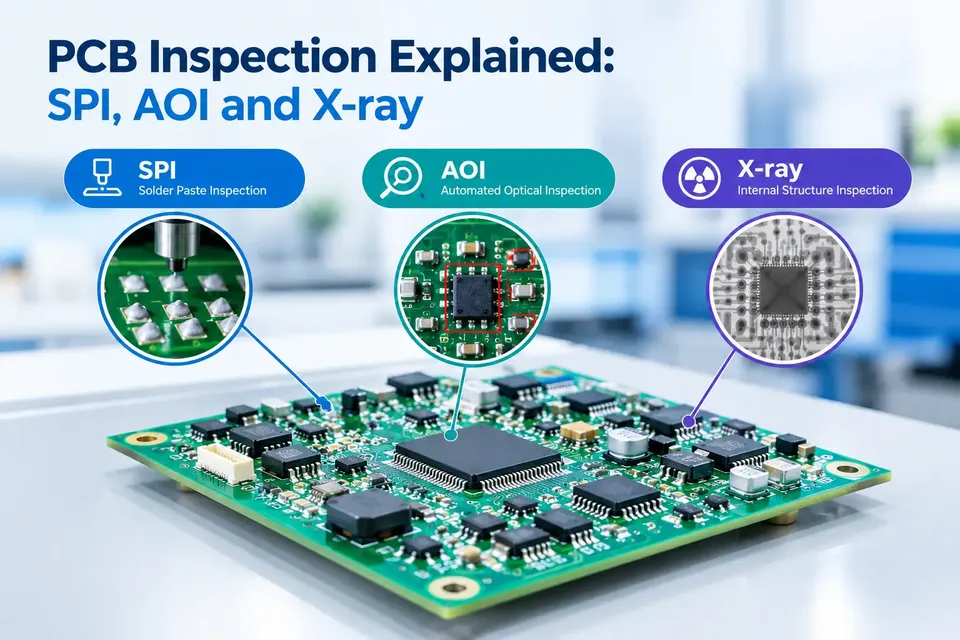
Polyfit's EMS division carries out functional testing alongside automated inspection (SPI and AOI), and builds to IPC-A-610. Talk to us about testing your board.
From precision components to custom manufacturing, Polyfit delivers solutions tailored to your application and specifications.
Request a quote